Chapter 3: Model Define — Geometry and Material
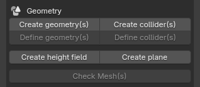
3.1 Geometry group layout
The Geometry group contains, from top to bottom:
- Create geometry(s) / Create collider(s)
- Define geometry(s) / Define collider(s)
- Create height field / Create plane
- Check Mesh(s)
3.2 Create Visual Geometry
Button: Create geometry(s)
Operator ID: forge.create_geometry
Dialog:
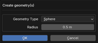
Available when no object is selected, or when every selected object is a Link, Frame, or Replicate.
- With no selection, create one Visual in World.
- With a selection, create one Visual for every selected parent object.
- Types: Box, Capsule, Cylinder, and Sphere.
- Dimensions:
- Box uses the three-axis Size;
- Sphere uses Radius;
- Capsule/Cylinder use Radius and Height.
After creation, the new Visual objects become the current selection.
3.3 Create Collider
Button: Create collider(s)
Operator ID: forge.create_collider
Dialog:
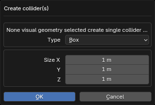
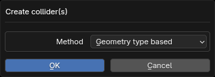
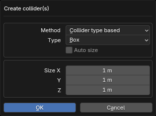
Available when:
- no object is selected;
- all selected objects are Link/Frame; or
- all selected objects are Visual.
When Visual objects are selected, there are two Method options:
- Geometry type: each Collider follows the type of its corresponding Visual.
- Collider type: every Collider uses one explicitly selected type. Auto size can automatically calculate dimensions for non-Mesh types. For Capsule / Cylinder, Use Min As Height takes the height from the visual's smallest bounding-box axis (and orients the shape along it) instead of the largest; it has no effect without Auto size.
With no selection or with Link/Frame selected, creation uses the specified Collider Type and Size.
3.4 Change Geometry / Collider type
Dialogs:
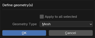
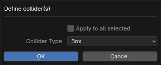
| Button | Operator ID | Applies to | Types |
|---|---|---|---|
| Define geometry(s) | forge.define_geometry_type |
Visual | Box, Capsule, Cylinder, Sphere, Mesh, Sdf |
| Define collider(s) | forge.define_collider_type |
Collider | Box, Capsule, Cylinder, Sphere, Mesh, Sdf |
The dialog starts with the active object's current type and modifies only the active object by default. Enable Apply to all selected to modify the whole selection. Changing type also switches or rebuilds the corresponding shape.
SDF uses an existing mesh: define a Visual as Sdf to export type="sdf" with a mesh asset reference. Switching between Mesh and SDF preserves the mesh; switching from a primitive first applies its shape modifier. Converting a primitive to Mesh or Sdf preserves its material slots, material assignments, and active material slot, without changing other objects sharing the original mesh.
Colliders also support Sdf. Select a Visual and choose Sdf in Create collider(s) to share its Mesh Data as a linked duplicate, preserving its parent and transform. Vertex edits affect both objects. Use Define collider(s) to change an existing collider. SDF colliders use mesh inertia computation and export as type="sdf", reusing the visual's mesh asset when shared or an STL asset when exported alone.
3.5 Height Field and Plane
These two buttons are available only when no object is selected, and create the result in World. They currently have no dialog.
| Button | Operator ID | Result |
|---|---|---|
| Create height field | forge.create_height_field |
Create a Height Field; edit detailed parameters in Properties. |
| Create plane | forge.create_plane |
Create a Plane; edit detailed parameters in Properties. |
3.6 Mesh Check
Button: Check Mesh(s)
Operator ID: forge.mesh_check
Available only when every selected object is a Visual. It checks whether the meshes satisfy the requirements of later operations such as inertial calculation and displays errors and elapsed time in the status/report area.
- Check whether the Visual model is manifold.
- Check whether Visual models intersect.
Compute Inertial validates geometry only when Check Geometry is enabled (off by default), using its chosen Visual / Collider source. If validation fails, repair open, degenerate, or otherwise invalid meshes first.
3.7 Material group
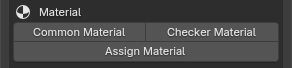
Button: Common Material
Operator ID: forge.create_material
Dialog:
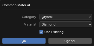
Available when all selected objects are Visual, Height Field, or Plane. It creates a parameter-only material:
- Choose a Category from the Forge PBR Library.
- Choose a Material.
- When Use Existing is enabled, an existing Blender material with the same name is reused first.
- On confirmation, assign the reused or newly created material to the first Material Slot of every selected object. Reusing preserves existing material settings; creating uses the library parameters. Visual, Height Field, and Plane all use an object-level material slot.
A suffix at the end of the material name selects the exported MJCF alpha_mode:
| Name suffix | Exported alpha_mode |
|---|---|
_blend |
blend |
_mask |
mask |
_multiply |
multiply |
The suffix is part of the material name, so the exported <material name> keeps it as well. Without one of these suffixes the MJCF default opaque mode is used.
• Assign an existing material
Button: Assign Material
Operator ID: forge.assign_material
Dialog:
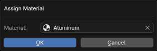
- Select one or more Visual, Height Field, or Plane objects.
- Click Assign Material in the Material group.
- Choose an existing Blender material from the searchable Material dropdown and confirm. The dialog initially selects the active object's material when available.
The selected material is assigned to the first object-level Material Slot of every selected object, creating the slot if needed. Other slots are preserved. This reuses the existing material, including its shader nodes and settings, without creating a copy. Unselected objects keep their assignments, including objects sharing the same mesh. Create or import a material first if none are available.
• Create a checker material
Button: Checker Material
Operator ID: forge.create_checker_material
Dialog:
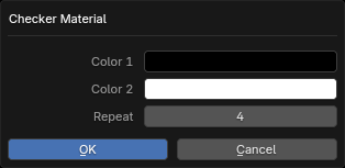
Select one or more Visual, Height Field, or Plane objects, then click Checker Material in the Material group. Every selected object must be one of these types.
| Parameter | Meaning | Default |
|---|---|---|
| Color 1 | First checker color | Black |
| Color 2 | Second checker color | White |
| Repeat | Integer repeat count along both UV axes, from 1 to 128 | 4 |
Confirm to create a new material and assign it to the first object-level Material Slot of every selected object. Each invocation creates a new material; selected objects share that material.
The generated shader uses Texture Coordinate (UV) → Mapping → Checker Texture → Principled BSDF (Base Color). Repeat sets Mapping Scale X and Y; Z remains 1. The Checker Texture node's Scale is 2. Keep this node layout and Scale when editing a checker for MJCF export; adjust tiling with Mapping instead.
Export writes a native MJCF <texture type="2d" builtin="checker"> and an RGB texture layer on the material, without baking or writing an image file. Color 1 / Color 2 become rgb1 / rgb2, with linear Blender colors converted to sRGB. Mapping Scale X/Y becomes the material's texrepeat; matching values produce texuniform="true", otherwise false. The texture is written before the material that references it.
With Import material enabled, importing an MJCF 2D builtin checker restores the UV, Mapping, and Checker Texture nodes, colors, and texrepeat. Both a material's texture attribute and RGB/RGBA <layer> references are supported. Imported U/V repeat values may differ; the creation dialog's Repeat sets both axes together.
• Create a custom material
The image below shows a complete custom material with texture maps. Each of the four framed sections can be disconnected from the BSDF node and replaced with the BSDF's direct parameter. The scene exports either parameters or textures depending on whether a node is connected to the BSDF input.
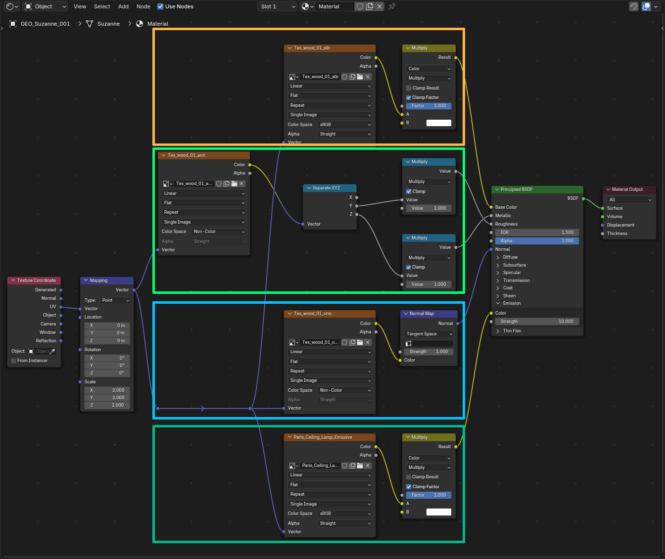
For image textures, follow the node layout above. For procedural checkers, use the checker layout described in the previous section. A parameter-only material does not need any node connected to the BSDF node. If tiling is not required, the Mapping node does not need to be connected to the texture node.