Chapter 0: UI overview and common operations
0.1 Open the Forge panel
After installing and enabling Forge, press N in the 3D View to open the sidebar, then switch to the Forge tab.
This documentation set covers the following UI panels:
- General information about Forge tools.
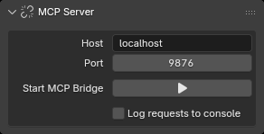
- MCP service configuration; see Chapter 1.
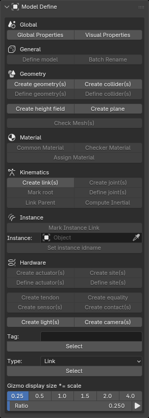
- Global settings, type definitions, model-element creation, and helper tools; see Chapters 0 and 2–5.
- Global:
Global Properties and Visual Properties.- General:
Define model and Batch Rename.- Geometry:
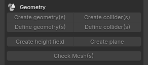
Create and define Visual/Collider shapes, Height Field, Plane, and Check Meshs (manifold and intersection checks).- Material:
Create common materials from the Forge PBR library, create checker materials, and assign existing materials.- Kinematics:
Link, Joint, Parent, Inertial, and Root.- Instance:
Mark, Choose, and Set.- Hardware:
Actuator, Site, Tendon, Equality, Sensor, Contact, Light, and Camera.- Tag / Select:
Select scene objects by name tag.- Type / Select:
Select scene objects by type.- Gizmo display size:
Adjust the display size of Forge gizmos in bulk.
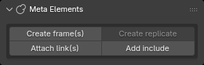
- Frame, Replicate, Attach, and Include; see Chapter 6.
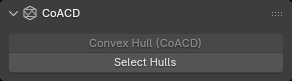
- Use CoACD to decompose a mesh into convex pieces; see Chapter 9.
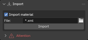
- Import an MJCF XML file; see Chapter 8.
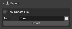
- Export an MJCF XML file; see Chapter 8.
Hover over a button or parameter to see its available tooltip. Blender's Object Properties → Forge Properties also exposes the active object's transform, parent, Forge type, and model properties; see Chapter 7.
0.2 Selection, active object, and selection order
- Selected objects: all objects currently selected.
- Active object: the last object activated, normally shown with a brighter outline.
- Forge type: the object's
Forge_Model_Type, such asLINK,VISUAL, orJOINT. - Selection order: Forge records the order in which objects were selected and uses it to assign roles such as Target, Reference, and parent.
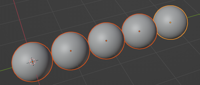
A Creation Operator usually creates one object for every selected target; a Definition Operator modifies only the active object by default. Pay particular attention to selection order for
Equality,Sensor,Light,Camera, andTendon, which use two or more targets.
0.3 What a disabled button means
A grey button means that the operator's preconditions are not satisfied. Common causes include:
- the wrong number of objects is selected;
- a selected object has an unsupported Forge type;
- an object should be deselected but is still selected;
- there is no valid active object; or
- Blender is not in Object Mode.
The exact conditions for each feature are listed in the tables in the later chapters.
0.4 Tags, model type selection, and viewport display
Select by tag
- Enter the text to match in Tag.
- Click Select to call
forge.select_by_tag. - Forge selects objects in the current scene whose names contain the text; the existing selection is not cleared automatically.

Select by model type
- Choose a Forge model type such as Link or Collider in Type.
- Click Select below it to call
forge.select_by_model_type. - Available only in Object Mode. Matching objects from the current context's selectable objects are added to the existing selection.

Adjust gizmo size
- Choose Scale factor or Ratio.
- Click the execute button on the right to call
forge.scale_gizmo_size. - If objects are selected, only those objects are changed. With no selection, all objects in the
.blendfile, including objects in other scenes, are changed.
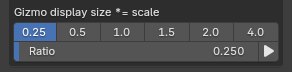
Inertial display dimensions are determined by mass and inertia and are excluded from this scaling operation.
Viewport preview toggles
Open Blender Preferences → Add-ons → Forge → General → Viewport Previews. Collider Preview and Inertial Preview are enabled by default and control translucent collider surfaces and equivalent inertia boxes in all 3D viewports.
Both previews require Overlays and Extras in the current viewport. Selected previews are orange; unselected Colliders are pale blue and Inertials are red. Collider objects use wireframe display, which remains available when surface previews are disabled. Disabling Inertial Preview retains its selectable native Empty box.
0.5 Recommended modeling workflow
- Create or import Mesh into Blender.
- Use Define model to define meshes as Visuals or Colliders. Create Links with Create link(s), or define an Empty as a Link. Primitive shapes can also be created directly with the creation buttons.
- Build the Link hierarchy and use Link Parent to adjust parent-child relationships.
- Create Visual, Collider, Joint, and Site objects.
- Create Actuator, Tendon, Equality, Sensor, Contact, Light, and Camera objects.
- Edit parameters with the viewport Gizmo.
- Run Compute Inertial on the Link, choose Visual / Collider, and enable Check Geometry as needed.
- Select the top-level Link/Frame and run Mark root.